nlight wiring diagram
Nilight 16awg wiring harness kit 12v with 5pin laser on off led light bar rocker switch 2 lead 2 years warranty. Device types include occupancy sensors.
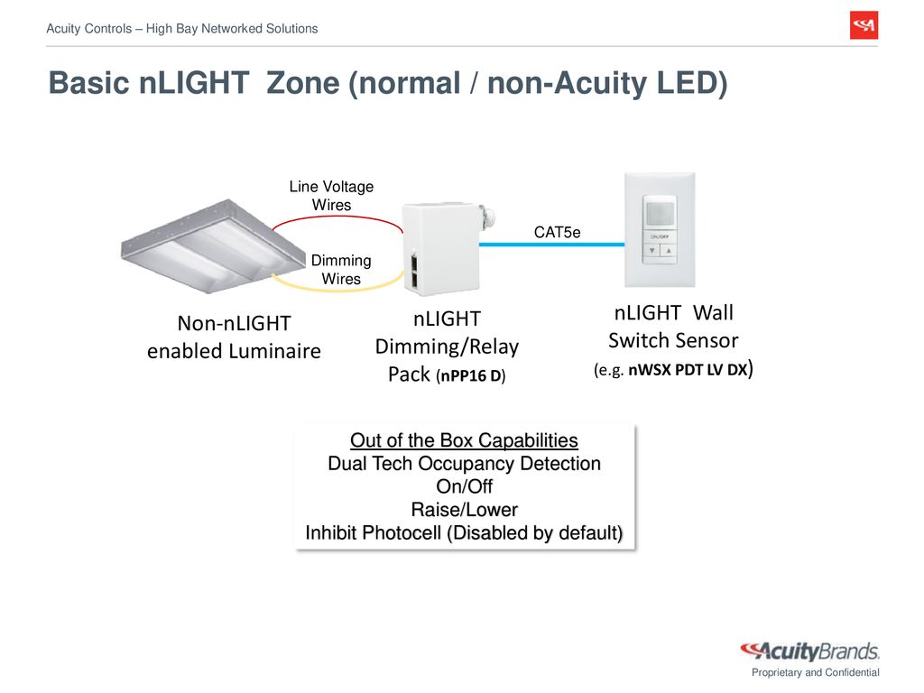
Acuity Controls High Bay Networked Lighting Solutions Ppt Download
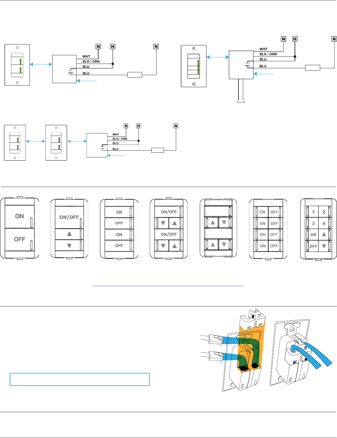
All wiring must comply with electrical wiring diagrams as well as national and local electrical codes.

. Nlight enabled fixtures wiring diagram. 11 Pics about 1991-1993_wiring_diagramgif FZROnline WIKI. Wiring Diagram For Multiple Lights - 31 Common Household Circuit nWSX.
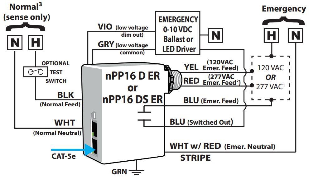
The nLight nPP16 Series power pack is the workhorse of an nLight system. Blink Codes nLight devices show status and diagnostic codes by blinking their LEDs in defined patterns. The T568B wiring standard is.
We recommend using CAT5 cable to connect the nLight UNITOUCH to the controller. The nPS 80 has two RJ-45 ports each. This diagram illustrates wiring for one switch to control 2 or more lights.
Any time connecting electrical cabling to an outlet it may be important to not confuse your wires or push them in the wrong airport terminal. The source is at SW1 and 2-wire cable runs from there to the fixtures. Nlight air enabled fixture 1 rpodb dx g2 onoff.
Lighting is a critical contributor to the. This is the system flexibility of a image i get from the dali lighting control. Sensor switch nlight wiring diagrams - 120277 vac wiring black line 1 input black load 1 output blue line 2 input blue load 2 output notes.
Using wire nuts connect line and low voltage wires as shown in the applicable wiring diagram in accordance with state local and national codes and requirements. CONTENTS 1 nLight Control System Overview 04 11 Introduction 04 12 System Architecture 05 121 nLight Enabled Device 05 122 nLight Control Zone 06 123 nLight Channel 07 124. The nPS 80 has two RJ-45 ports each that is current limited to 40 mA making wiring with standard CAT-5 cabling easy and clean.
Once linked to a gateway directly or via a bridge Product image model name cad symbol description. Wiring Diagram For Multiple Lights - 31 Common Household Circuit nWSX. NLight AIR is wireless lighting control within the nLight platform delivering networked lighting controls that are easy to specify.
Nlight eclypse wiring diagram QSTIONCO - Consider a simple office with an npodm wall switch and a power pack wired to the rooms light fixture. CAT-5e network cable to connect nLight devices. Wireless Lighting Controls with Unmatched Flexibility.
Multiple Light Wiring Diagram. Provides System Power over CAT-5. The nLight AIR rPODLA is a wireless line-powered wall switch providing a user with local control of a lighting zone featuring onoff raiselower multi-pole and scene control.
The nLight lighting controls platform makes it simple to specify design install and setup helping to achieve code compliance with either CAT 5e wired controls that work out-of-the-box or.

Sensor Switch Nlight Digital Lighting Control Youtube
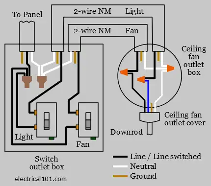
Ceiling Fan Switch Wiring Electrical 101

Color Annotated Wiring Diagram 98 And Up Www Drriders Com

Rotary Wall Dimmer Switch 0 10v Rf Dimming T18 2
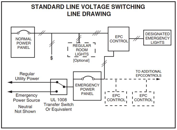
Lvs

Nlight Power Relay Pack Instruction Manual Manuals
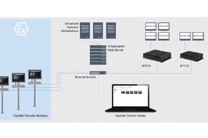
Pepperl Fuchs Mensch Und Technik Im Direkten Dialog Git Sicherheit De Portal Fur Safety Und Security

Lightflex Led Nlight Controls Start Up And Programming Made Simple Youtube

Nlight Wired Networked Lighting Controls
Product Detail Manual

Sensor Switch Npp16 D Efp Nlight Dimming Emergency Relay Pack 120 277v Amazon Ca Electronics

Solution Diagram Control Panel Designs
Nlight Network Lighting Control 2014 Acuity Brands Lighting Inc Pdf Free Download

Flame Propagation Mode Transition Of Premixed Syngas Air Mixtures In A Closed Duct Sciencedirect

N Light Switching Youtube

Modern Vespa T5 Mk1 Wiring Diagram
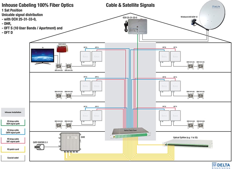
Oft S 10 Optischer Unicable Multischalter Dct Delta